55 HT project page 35
Still working on the brakes and clutch setup...
Still getting way too many leaks, have had to pull off
just about every one of these steel brake lines and
redo the flares, and try different connectors....
These are 60" steel brake lines from NAPA,
but I am getting leaks from just about every one
of their flared ends, it's been a nightmare !!
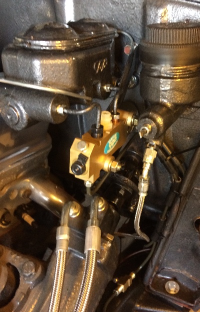
The front line for the disk brakes goes down to a tee,
then off to both sides for the front brakes....
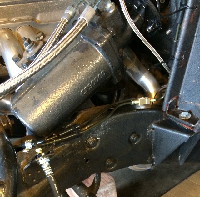
The rear line for the drum brakes is routed along the outside
of the left frame rail, using rubber hose and clamps...
Two 60" pieces, one from the MC down and back,
and one from the rear end hose forward, then
cut and flare this piece in the middle to tie it together....
Routed it around the body mount so it wouldn't rub anywhere...
Not a very good pic but the line is routed up and over the
frame rail at the rear to a mount for the rubber hose
to the rear axle...
Got it bled and all the brakes are working,
but there are still some small leaks among
the connectors that I'm trying to tighten up....
Got the hydraulic clutch system bled and hooked up,
but I'm getting a much higher foot pedal pressure than
I should, so have to check that out now....
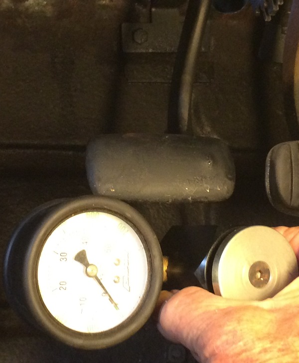
Dug out my valve spring compression gage....
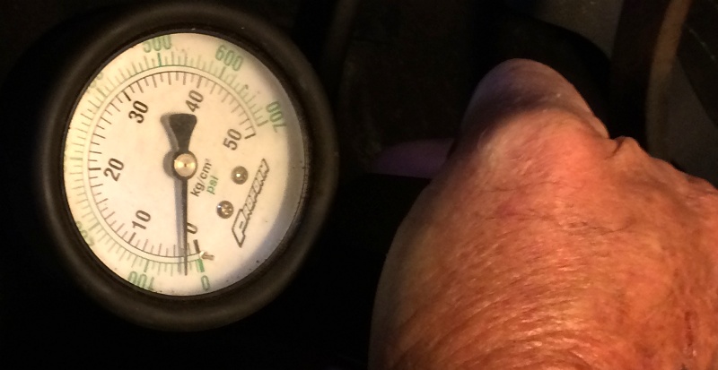
....And used it to press against the clutch pedal,
it's running between 35 and 45 lbs pressure, so I'll use 40 average,
with this system I designed the mechanical leverage factor
is 5.5 to 1, so with 40 lbs at the pedal I'm putting 220 lbs
on the clutch release lever at the slave cylinder...
For this aftermarke '93 LT1 T56 clutch setup I
don't know if that is excessive or not.
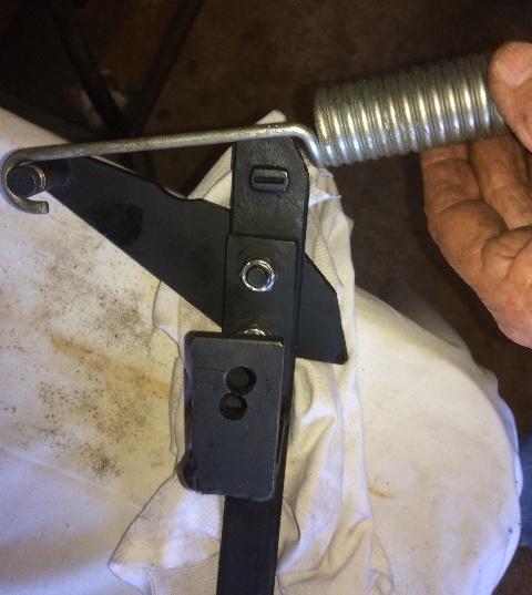
Tried to install the clutch pedal "over center/return spring" but it was too loose
with the oem anchor, the lower one, so I made up a shorter/adjustable one....
It fits like this with the front hook located so that the pedal pivot
passes through the plane of the springs pull in such a way that
when the pedal is up the spring holds it up, and when the pedal
is depresses the spring assists in pushing against the
mastercylinder. I got it installed and adjusted so that it
feels pretty good....
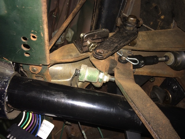
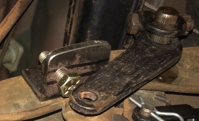
The clutch pedal needed a stop for when I took my foot
off of it, as the original lever on the right side of the
pedal pivot was not being used, I fabbed an adjustable
stop and put it in there....
A close up....
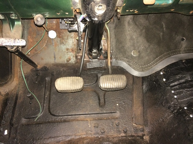
After aedjusting the push rod for the master cylinder, I had about
a 1/4" of "free play" before the push rod touched anything in the MC,
the over center / return spring is working perfectly to hold the pedal
up against the stop and sitting at the same level as the brake pedal
right next to it.
The brake pedal feels good, and the clutch pedal feels pretty good also,
a slightly heavier clutch pedal feel than the mechanical one in my
'55 gasser, and I think it will be ok....
Been away from this project for awhile,
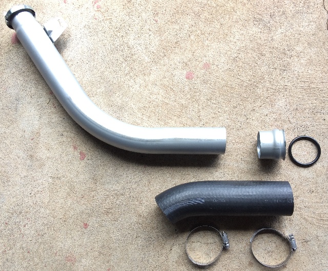
ordered a ss fuel filler tube, it's supposed to
fit my '55 Chevy hardtop, just as the fuel tank
I bought is supposed to fit, but this fuel filler
tube is too short, so thought I'd just extend it with
some 2" ID fuel hose I have on hand....
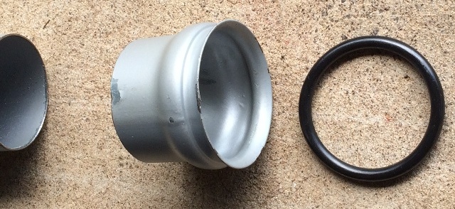
It needs to be about 3" longer at the fuel tank,
so I cut off the O-ring portion and did a trial fit....
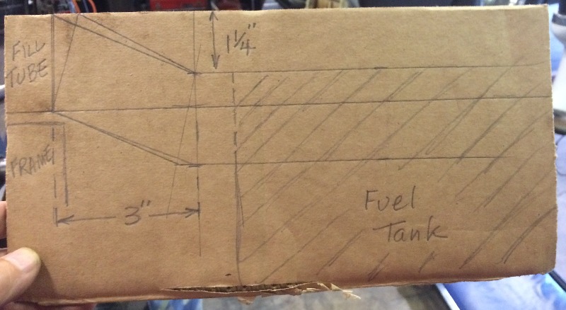
It won't work, the tank inlet is partially below the frame,
I couldn't get the rubber hose to bend that much,
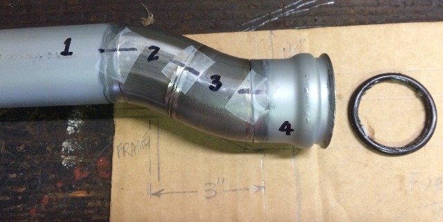
so I bought a 45 deg bend piece of ss 2" pipe
and drew up as accurate a sketch of what needed
to fit where as I could....
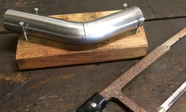
......and started cutting to fit....
Cutting by hand with a hack saw gives me the thinnest
cuts when I want precision fitting of the pieces...
Now to cut each piece to get the correct length
in the middle....
This matched my drawing pretty well,
now to tack it together and see how well it fits
in the car and into the fuel tank
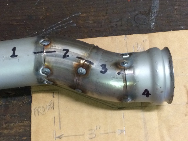
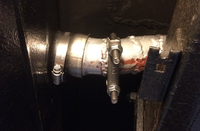
It fits quite well, now to weld it up, test for leaks
and paint it...
With the O-ring on it, the fit was so tight into the
fuel tank receiver that a 2" clamp had to be appled
and even with lube a pry bar was needed to get the
O-ring to go into the fuel tank receiver....
More Later....

