62 FL Chop Rebuild 25
Page 25
I need to get this ride finished and out on the road!!
Now that I got the heads shifted away from each other
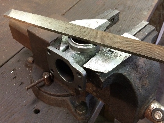
about 20 thou, I can get the intake in there, but it is too tight,
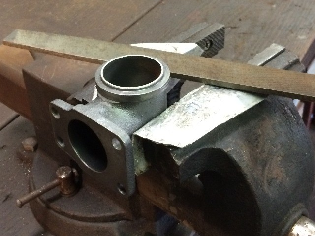
so got the mill files out and removed a little on each side
of the intake tee....
Ended up taking a total of 5 thou off, half on each side....
It left some sharp edges, so smoothed them out
with some emery cloth....
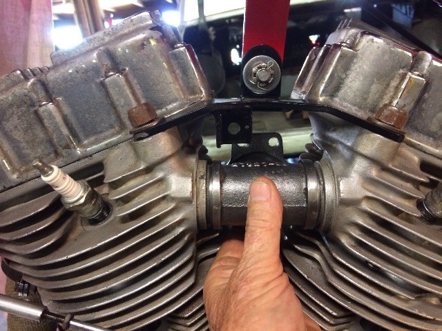
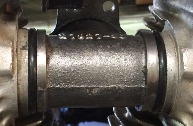
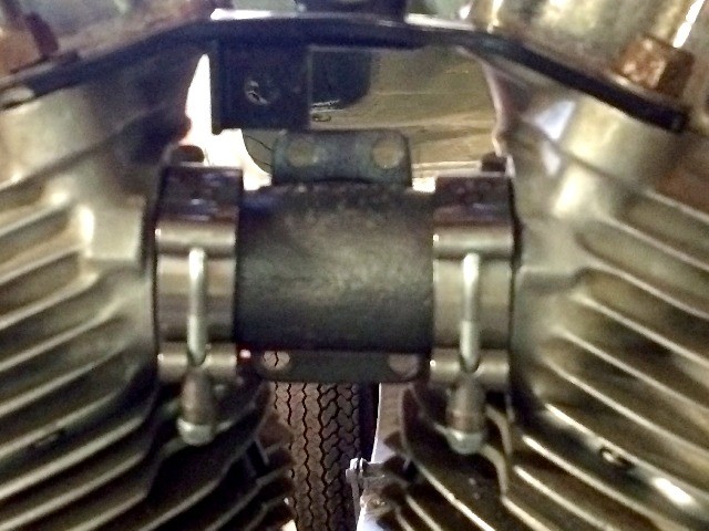
Ahhh, a perfect fit, slides right in with no slop at all...
Put the O-rings on, but do not like the clamps shown previously,
looking for the oem style clamps, have some around here somewhere....
Now back to my carb, Indian Head shellac was recommended to
seal the float attachment, my local hardware store has this,
I wonder if it will work ok?
I went ahead and sealed off the screw, nut, and mount
on the float with this product, guess I'll find out
if there is a problem with it, but I seriously doubt that....
Look what I found !!!
It was quite a "wrestling match" to get those clamps, along with the
O-rings, and the tee intake, into position between the heads....
Next was timing the mag, as I had to pull the mag to loosen the
head bolts and get the intake tee to fit, now that it is all snugged down,
I rolled the front piston into compression mode and brought the flywheel
up to the "three dots"......
(If you missed it, it's here.....)
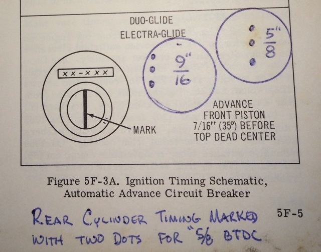
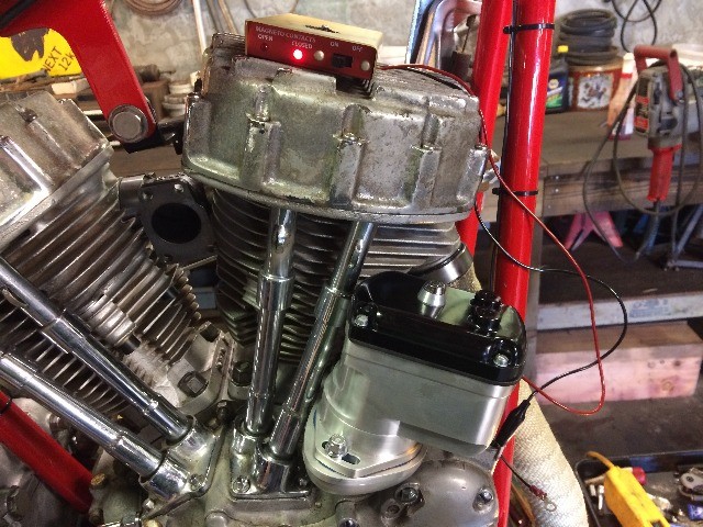
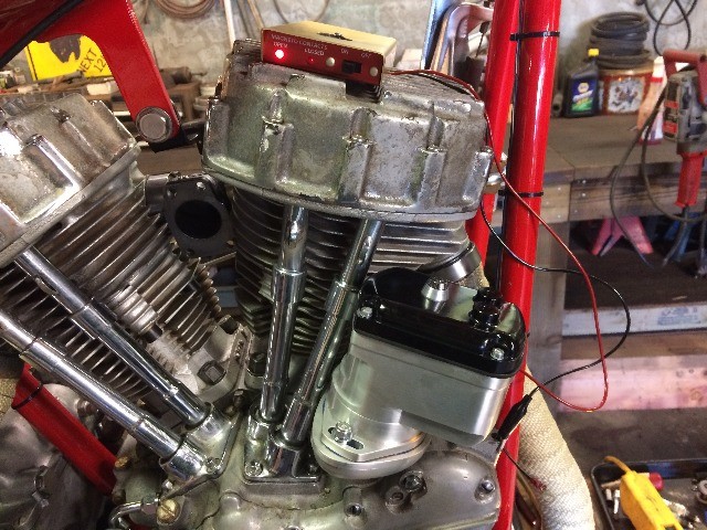
Got it close, and hooked up my little mag style timing light....
Rotated the mag between the "not fired yet" light....
And the "fire" light, got it right on the money and tightened it down....
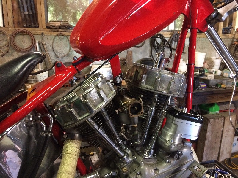
Mounted the carb....
And started looking at what I need to hook up the fuel...
This was taped up, and when I pulled off the tape, I found this...
I can clean up the rust, no problem there,
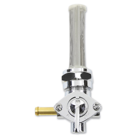
This is a 22 mm fuel bung thread,
HD used this thread starting somewhere in the mid 80's....
Looking at something like this....
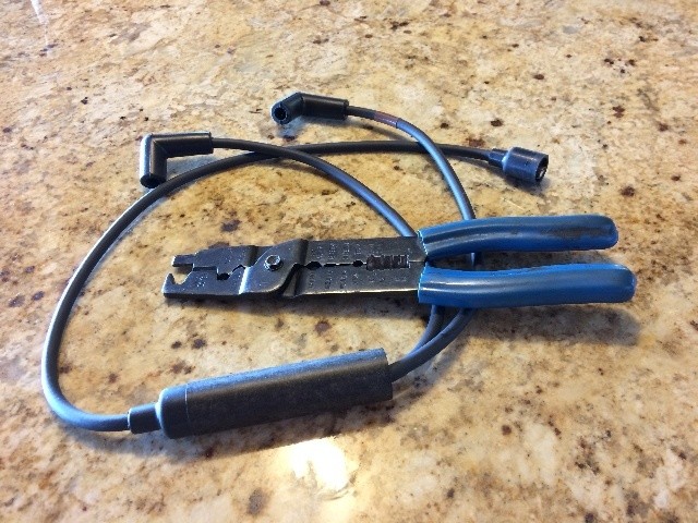
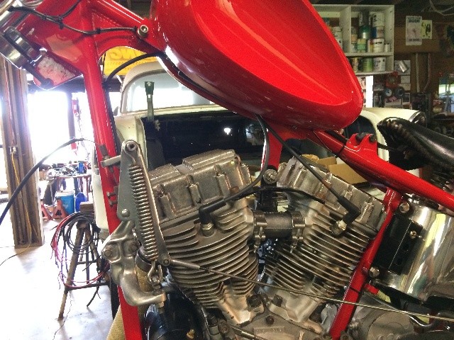
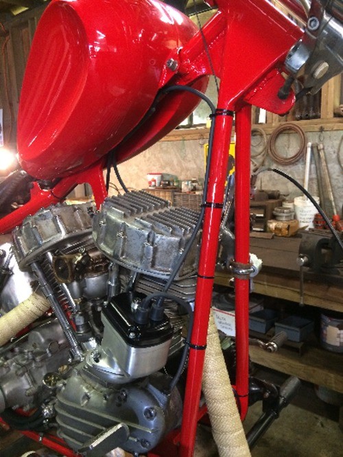
Meanwhile, the single fire Morris ignition leads were cut to fit
and terminals were clamped on the ends...
This is a pretty cool system, there are huge capacity diodes in that large piece
in the middle of the wires that direct the spark to one or the other spark plug,
instead of firing both spark plugs as the normal HD system does.
It can do this because the magneto system reverses polarity of the spark
each time it fires, and sends fire to both spark plugs, giving wasted spark to
the cylinder that is in exhaust stroke mode....
These diodes are set up to function opposite each other, so when there is a
positive polarity originating from the magneto, it goes to only one spark plug,
and as the next spark is a negative polarity, it goes to the other spark plug.
That way only one spark plug is fired, on the compression stroke, with
a hotter spark, and no wasted spark on the cylinder with the exhaust stroke.
One side of the magneto output is grounded, and the other side
is connected to the pair of diodes...
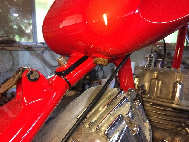
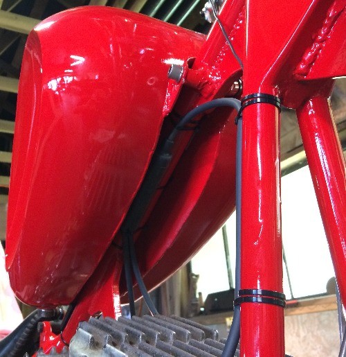
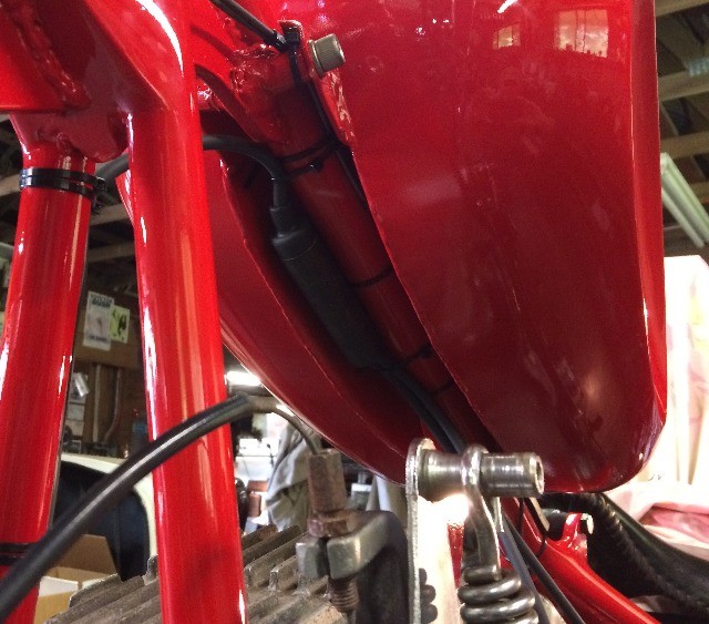
I tied the diode unit under the fuel tank....
Most folks wouldn't even notice it up there....
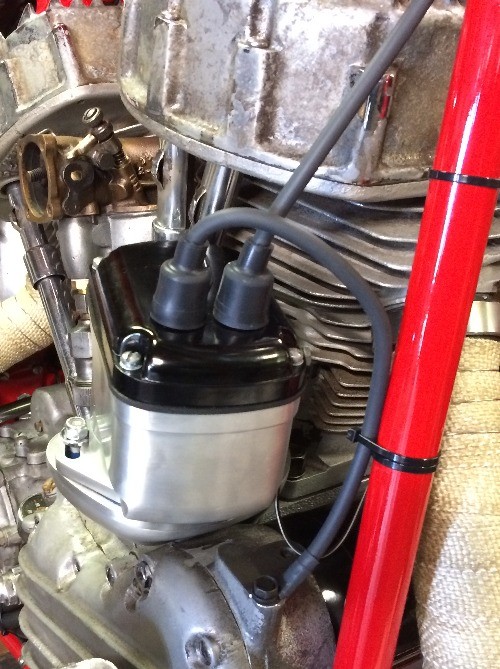
If I have the wires on the wrong cylinders, I'll just swap 'em....
It's a clean looking setup....
Swapped out the mag cap for a keyed unit, so I can lock out the magneto if I need to...
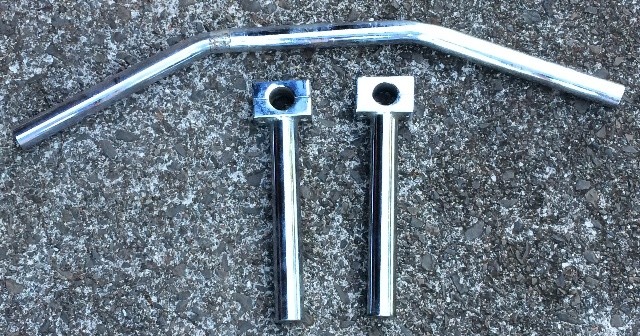
I'm jones'n for my old setup with flat bars....
Pulled the bars offa the shelf, and
found a local set of 9" risers. gonna use 'em...
More Later

